
Modern tournament bass fishing and shallow-water competitive angling platforms rely heavily on high-frequency broadband CHIRP (Compressed High-Intensity Radiated Pulse) acoustic sounders. Unlike legacy single-frequency 50/200 kHz echo sounders that transmit short, unmodulated continuous-wave pulses, broadband CHIRP transducers sweep linear frequency-modulated (LFM) signals continuously across wide spectrums (typically Low CHIRP: 28-60 kHz, Medium CHIRP: 85-135 kHz, and High/Super-High CHIRP: 130-250 kHz). Delivering instantaneous acoustic transmission power between 1 kW and 3 kW into raw water loads generates extreme electrical displacement currents across vessel grounding planes.
When high-voltage acoustic ping bursts travel alongside high-speed digital video streams, severe electromagnetic interference (EMI) frequently distorts helm chartplotter displays. Without robust isolation and shielding, low-amplitude return echoes from deep thermoclines and bottom-hugging gamefish become completely obscured by electronic noise artifacts.
1. Acoustic Near-Field Coupling and Galvanic Ground Shifting
In high-power acoustic transducers (such as Airmar B175H or dual-channel live-scanning elements), piezoceramic crystals act as dynamic reactive loads. The peak transmission voltage reaches up to 1200V peak-to-peak into impedance matching transformer networks. If the cockpit touch display shares an unisolated direct-current (DC) power distribution system with the sonar drive amplifier, the rapid rate of current rise excites parasitic inductances in common negative lines.
Induced Ground Transient Formula: V_ground_spike = L_gnd × (di / dt) Where L_gnd ≈ 1.2 μH per meter of chassis cabling, and di/dt reaches 1.5 × 10^7 A/s during 3 kW bursts. Resulting Peak V_spike = 1.2 × 10^-6 × 1.5 × 10^7 = 18.0V transient offset across digital ground.
Because the high-speed Low-Voltage Differential Signaling (LVDS) or embedded DisplayPort (eDP) data buses running between the timing controller and the TFT panel operate with differential logic thresholds of only ±100 mV to ±300 mV, an 18V transient offset exceeds the receiver common-mode rejection ratio (CMRR). This manifests on the angler’s display as severe horizontal line jitter, periodic frame freezes, or display controller reset cycles.
To eliminate these catastrophic ground differentials, high-performance bridge architectures deploy dedicated hardware like the Bass Boat Fish Finder Touch Monitor CHIRP Sonar Display, which incorporates a multi-stage isolated DC-to-DC converter with 1500V DC galvanic breakdown protection, bidirectional common-mode chokes, and decoupled isolated ground planes.
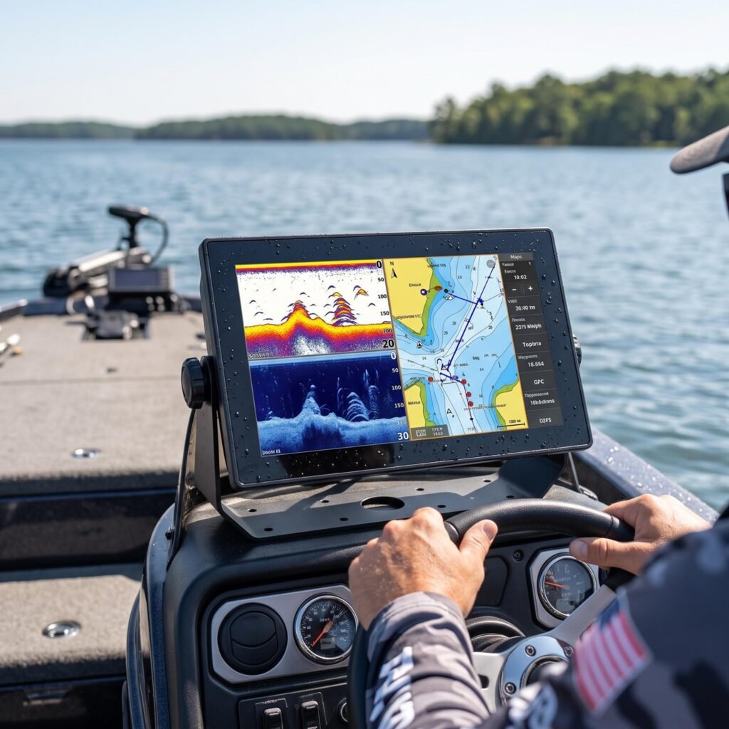
Bass Boat Fish Finder Touch Monitor (CHIRP Sonar Display)
Engineered for bass fishing cockpits and tournament skiffs. Features 1000-1500 nits sunlight readability, full optical bonding, complete IP67 waterproofing, and high-EMI shielding against high-power broadband CHIRP acoustic transducers.
2. Radiative Chassis Shielding and Touchscreen Noise Immunity
Projected capacitive (PCAP) touch screens operate by measuring micro-capacitance differentials (typically 0.1 pF to 1.5 pF) between orthogonal indium tin oxide (ITO) transmit (TX) and receive (RX) electrode matrices. When unshielded transducer cabling runs parallel to the display harness along narrow fiberglass boat gunwales, radiated electromagnetic fields couple directly into the capacitive sensing matrix.
- Continuous 360-Degree Faradization: Stamped sheet-metal housings with screw seams permit high-frequency electromagnetic leakage. A monolithic CNC-machined marine aluminum chassis provides a continuous conductive shield, maintaining chassis surface transfer impedance below 0.05 Ω across the 100 kHz to 300 MHz spectrum.
- Adaptive Frequency-Hopping DSP: The touch controller’s digital signal processor scans background electromagnetic noise in real time before driving sensing pulses. When active CHIRP sonar excitation is detected, the DSP shifts its scan drive frequency away from acoustic harmonics (e.g., jumping from 120 kHz to 230 kHz) within 4 milliseconds.
- Optical Wet Bonding Barrier: Solid liquid optical clear adhesive (LOCA) eliminates the dielectric air boundary between the cover glass and the sensor glass, stabilizing baseline mutual capacitance against ambient humidity and spray electrostatic discharge.
Sonar Interface & Display Hardware Specification Matrix
| Engineering Metric | Standard Marine Screen | Engineered IP67 CHIRP Sonar Display |
|---|---|---|
| Galvanic DC Isolation | Non-isolated common ground (Subject to ground loop currents) | 1500V DC optical/magnetic galvanic barrier on power & data |
| Touch Noise Suppression | Fixed-frequency excitation (Locks up under 200kHz pings) | Dynamic frequency-hopping DSP with real-time SNR filtering |
| Chassis Shielding Integrity | Plastic enclosure with partial metal spraying | Heavy CNC anodized marine aluminum with conductive gasket |
| Optical Construction | Perimeter tape-bonded air gap (Prone to internal fogging) | Full optical wet bonding (Refractive index n=1.51) |
| Transient Engine Surge | 9-16V DC narrow (Drops out during outboard cranking) | 9-36V DC wide input with 100V load-dump surge clamp |
3. Step-by-Step Field Installation Guidelines
- Separate Cable Routing: Maintain a minimum physical spacing of 15 cm (6 inches) between the transducer coaxial transmission line and the DC power/video harness of the display. If cables must intersect, route them at 90-degree angles to minimize inductive coupling.
- Single-Point Vessel Grounding: Connect the dedicated chassis grounding lug of the display directly to the central battery negative busbar using 10 AWG tinned marine copper wire. Never daisy-chain the display ground to nearby navigation lights or bilge pumps.
- Ferrite Core Termination: Place split-core high-frequency ferrite chokes (rated for 10-100 MHz impedance) within 5 cm of the display power and video input connectors to choke off high-frequency common-mode return currents.
Selecting display hardware with verified galvanic isolation and active EMI shielding ensures uncompromised target discrimination when tracking baitfish and thermoclines at maximum acoustic power. Contact INNODA’s marine engineering team to review custom bridge dimensions, NMEA 2000 compatibility, and multi-sensor integration options.