
Self-service payment kiosks, automated hospitality check-in terminals, and industrial plant access-control stations frequently integrate magnetic stripe readers (MSR) directly into the computing bezel. A compact 10.4-inch 4:3 form factor (800×600 or 1024×768 resolution) provides an optimal physical balance for counter-top mounting and turnstile integration. However, embedding an analog magnetic pickup head within millimeters of high-speed digital computing circuits introduces severe electromagnetic interference challenges.
Magnetic stripe card readers operate by sensing minute magnetic flux transitions as a ferrous oxide stripe slides across a permalloy core. When unshielded switching power supplies, high-frequency CPU memory buses, or LCD backlight inverters radiate near-field electromagnetic noise, the magnetic read head picks up spurious signals, causing high bit-error rates (BER) and failed card swipes.
1. Faraday Induction Physics & ISO 7811 F2F Decoding Dynamics
Magnetic stripe cards store binary data utilizing Two-Frequency Coherent Phase (F2F) encoding according to the ISO/IEC 7811 standard. As the card is swiped past the read head gap, alternating magnetic domains induce microvolt-level transient signals in the pickup coil according to Faraday’s Law of Electromagnetic Induction:
Faraday’s Induction Voltage Formula: V_induced = -N × (dΦ_m / dt) = -N × A_core × (dB / dt) Where: – N = Number of pickup coil turns (≈ 500 to 1,200 turns of fine copper wire). – A_core = Permalloy core cross-sectional area (≈ 1.5 × 10^-6 m²). – dB/dt = Rate of magnetic flux density change during a manual swipe (v_swipe = 10 cm/s to 120 cm/s). Signal Output: At slow swipe speeds (10 cm/s), peak induced signal V_induced drops to only 0.8 mV to 1.5 mV peak-to-peak. Noise Threshold Hazard: If nearby switching regulators radiate noise exceeding 300 μV into the analog coil, signal-to-noise ratio (SNR) collapses below 10 dB, corrupting F2F clock recovery.
Because the analog voltage generated by a slow manual card swipe is minute, unshielded wires picking up radiated harmonics from the mainboard’s switched-mode power supplies cause the peak-detector comparator to falsely trigger on noise spikes, leading to frequent “Card Read Error” prompts.
To ensure high read reliability across millions of transactions, financial and access-control builders standardize on the 10.4″ Touch Panel PC with Magnetic Card Reader, which isolates the magnetic read head within a dedicated mu-metal magnetic shield enclosure while deploying hardware differential pre-amplifiers.
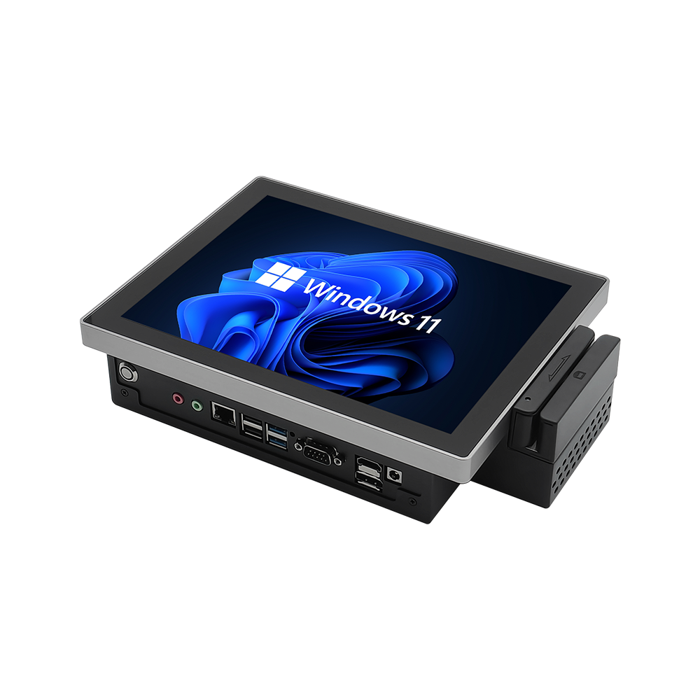
10.4″ Industrial Panel PC with Magnetic Card Reader
Engineered for access control turnstiles, self-service ticketing kiosks, and POS checkout stations. Features an integrated 3-track ISO 7811 magnetic stripe reader, 10.4″ industrial LCD with 5-wire resistive or PCAP touch, and robust EMI/ESD isolation.
2. Mu-Metal Magnetic Shielding & Galvanic Decoupling
Suppressing both high-frequency electric fields and low-frequency magnetic hum requires combining complementary shielding materials:
- Mu-Metal Permeability Barrier: The magnetic read head assembly is encapsulated inside an 80% nickel-iron mu-metal alloy housing. Boasting high relative magnetic permeability (μ_r > 80,000 at low flux densities), mu-metal diverts stray magnetic fields generated by internal inductor coils away from the pickup gap.
- Differential Preamplifier Architecture: The analog coil connects directly to a low-noise, balanced differential pre-amplifier situated adjacent to the read head. Common-mode noise induced equally across the differential pair is rejected by over 60 dB.
- Electrostatic Discharge (ESD) Shunt Ring: Card insertion slots are primary entry paths for static discharge when users carry charges up to ±15 kV. An internal stainless steel grounding track diverts ESD directly to the chassis frame before voltage arcs can reach sensitive read electronics.
Integrated vs. External Magstripe Reader Comparison
| Engineering Parameter | External Add-On USB Dongle | Engineered 10.4″ Integrated MSR PC |
|---|---|---|
| Magnetic Shielding | Unshielded plastic shell (High EMI bit errors) | Full mu-metal ferromagnetic isolation cavity |
| ESD Immunity Level | ±4 kV contact (Freezes USB host controller) | ±15 kV air / ±8 kV contact discharge protection |
| Head Mechanical Life | ≈ 300,000 passes (Soft permalloy core) | > 1,000,000 passes (Hardened ceramic/alloy head) |
| Chassis Integration | Exposed cables subject to tampering/snagging | Internal recessed slot flush with bezel frame |
| Vibration Durability | Vulnerable mounting brackets loosen over time | Solid CNC aluminum housing with shock standoffs |
3. Preventive Maintenance & Head Cleaning Protocol
- Magnetic Head Alcohol Cleansing: Every 10,000 card passes or monthly, insert an isopropyl alcohol (99% pure IPA) pre-saturated cleaning card through the swipe slot 5 times to dissolve accumulated skin oils, dirt, and ferrous dust particles.
- Track Alignment Verification: Check read consistency across ISO Track 1 (IATA 210 bpi), Track 2 (ABA 75 bpi), and Track 3 (TTS 210 bpi) using a calibrated reference test card to confirm physical head azimuth alignment remains within ±5 minutes of arc.
- Chassis Grounding Check: Verify that resistance between the kiosk card slot mounting bracket and the main facility earth ground measures less than 0.1 Ω to maintain static dissipation paths.
Integrating an EMI-shielded magnetic card reader into a rugged 10.4-inch panel PC eliminates peripheral cabling clutter and ensures smooth transaction processing in high-traffic kiosks. Contact INNODA’s kiosk hardware engineering team to review ISO 7811/EMV compliance data, API integration libraries, and custom enclosure finishes.