
Modern retail point-of-sale (POS) checkout stations, loyalty kiosk check-ins, casino gaming consoles, and industrial tool crib dispatch systems require compact operator interfaces that integrate physical credential verification. A 10.4-inch display format (4:3 aspect ratio / 800×600 SVGA or 1024×768 XGA resolution) provides an optimal physical balance for space-restricted service counters, delivering responsive graphical touch interaction alongside hardware-integrated card swiping. Combining computing logic, touch sensing, and a 3-track Magnetic Stripe Reader (MSR) into a single unified chassis eliminates loose desktop peripherals and tangled USB cables.
However, embedding an analog magnetic read head directly into an industrial touchscreen terminal introduces severe electrical noise and static discharge risks. Operators carrying high electrostatic charges (up to 15 kV in dry, air-conditioned retail environments) discharge directly into the metal card slot during swiping, threatening internal processor logic boards. Furthermore, high-frequency electromagnetic switching noise from display backlight drivers can couple into the low-voltage magnetic pickup coil, corrupting card bit streams. Specifying a durable 10.4-inch MSR terminal requires analyzing Faraday induction voltage physics, electrostatic discharge (ESD) shunting paths, and solid-state fanless thermal protection.
1. Faraday Induction Voltage Dynamics & Bitstream Frequency Modeling
Magnetic stripe cards store binary data across magnetic domains magnetized in opposite longitudinal directions. When an operator swipes a card past the read head gap, the moving magnetic flux induces a small electrical voltage in the pickup coil in accordance with Faraday’s Law of Electromagnetic Induction:
Faraday Induced Peak Voltage & Bit Frequency Equation: Induced Coil Voltage: V_ind = -N × (dΦ / dt) = -N × A_core × (dB / dt) Where: – Coil Winding Density: N = 1,200 turns. – Average Manual Swipe Velocity: v_swipe = 1.0 m/s (Nominal operating range: 0.3 m/s to 1.5 m/s). – ISO 7811 Track 2 Recording Density: ρ_bit = 75 BPI (bits per inch) ≈ 2,953 bits/meter. Spatial Flux Transition Wavelength: λ_domain = 1 / ρ_bit = 1 / 2953 ≈ 3.386 × 10^-4 m = 0.339 mm. Induced Signal Fundamental Frequency: f_signal = v_swipe / λ_domain = 1.0 / (3.386 × 10^-4) ≈ 2,953 Hz (~2.95 kHz). Peak Induced Analog Voltage: V_peak ≈ 15.0 mV to 45.0 mV (Millivolt level). Noise Margin Engineering: Because the raw induced signal is only ~30 mV, internal switching noise from LCD LED backlight drivers (operating at 20 kHz to 50 kHz) must be isolated with dedicated permalloy magnetic shields to prevent bit error drops.
Because the raw induced voltage is exceptionally small (under 50 mV), high-frequency electrical noise from internal switching regulators can easily swamp the signal. Integrating an internal magnetic shield around the read head preserves a Signal-to-Noise Ratio (SNR) exceeding 26 dB, guaranteeing error-free card reads on worn magnetic tracks.
To deliver rapid customer credential verification and high terminal reliability, retail automation builders deploy the 10.4″ Touch Panel PC with Magnetic Card Reader, which couples an industrial 3-track MSR module with an ultra-compact fanless panel computing chassis.
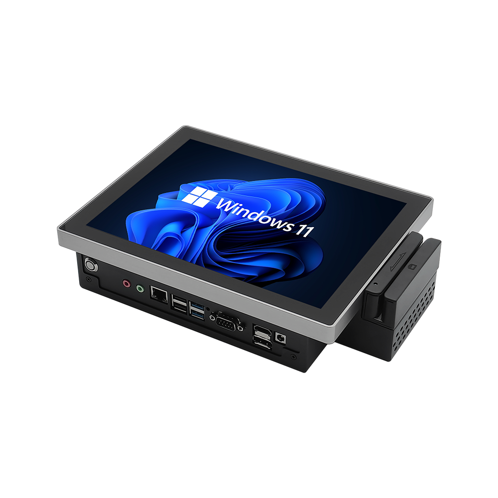
10.4″ Touch Panel PC with Magnetic Card Reader
Designed for retail POS counters, gaming terminals, and tool dispatch kiosks. Features an integrated 3-track magnetic stripe reader (1,000,000 passes), ±15 kV ESD static protection, 10.4″ classic 4:3 industrial LCD, IP65 front sealing, and fanless passive cooling.
2. 15 kV Air Electrostatic Discharge (ESD) Shunting Architecture
Unattended public kiosks and POS terminals face constant static discharge threats:
- Direct-Path Chassis ESD Shunting: The internal MSR read head frame connects directly to the outer aluminum chassis ground via low-impedance beryllium copper spring clips, diverting ±15 kV air and ±8 kV contact discharges safely to earth before transients reach the motherboard.
- 10.4″ 4:3 Industrial TFT-LCD Panel: Provides native 4:3 aspect ratio compatibility for legacy point-of-sale and industrial warehouse software, eliminating warped button layouts and stretched graphical menus.
- Solid-State 100% Fanless Architecture: Passive rear aluminum heatsink conduction eliminates cooling fans that draw dust and retail lint into card reader transport tracks, maximizing mechanical component lifespan.
Integrated vs. External MSR Terminal Technology Comparison
| Diagnostic Checkpoint | External USB Desktop Dongle | Engineered 10.4″ Integrated MSR PC |
|---|---|---|
| ESD Surge Immunity | ±4 kV (Crashes USB bus on static zap) | ±15 kV Air / ±8 kV Contact direct chassis shunt |
| Magnetic Head Lifespan | ≈ 300,000 passes (Consumer grade) | ≥ 1,000,000 passes heavy-duty alloy head |
| Cable Fatigue Vulnerability | High (Trailing USB cord snags and breaks) | Zero external cables (Internal isolated UART/USB) |
| Counter Space Footprint | Cluttered desktop footprint | Compact VESA 75/100 or panel-mount integration |
| Front Ingress Protection | Unrated (Spilled drinks destroy reader) | IP65 front splash-proof touch face |
3. Commissioning Guidelines for POS & Kiosk Integration
- Chassis Star Earth Grounding: Connect the terminal’s rear chassis grounding terminal to the kiosk structural frame using a heavy stranded ground lead (≥ 2.5 mm²) to ensure safe dissipation of high-voltage electrostatic charges.
- Magnetic Head Cleaning Protocol: Run an isopropyl alcohol-saturated MSR cleaning card through the swiping slot once monthly to remove airborne grease, skin oils, and particulate debris from the head gap.
- Touchscreen Edge Calibration: Execute a 4-point touch controller alignment check, verifying responsive touch registration near the right-hand card guide channel to ensure seamless user interaction.
Standardizing retail checkout consoles and automated access kiosks on 10.4-inch touch panel PCs with integrated magnetic card readers eliminates peripheral cable failures and prevents electrostatic downtime. Contact INNODA’s retail automation engineering team to request 3D STEP packaging files, MSR SDK integration documentation, and custom bezel finish options.