
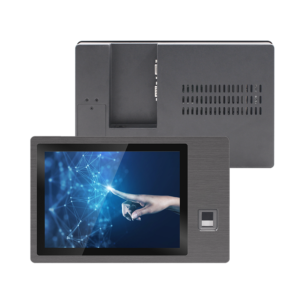
In high-security pharmaceutical suites, semiconductor cleanrooms, and automated biomanufacturing facilities, human-machine interface (HMI) access control terminals must satisfy two conflicting requirements: uncompromising biometric identity verification and seamless integration into low-voltage building infrastructure. Integrating an optical or capacitive fingerprint sensor directly into a sealed front bezel eliminates the need for external credential badges, which are prone to microbial contamination and physical loss.
However, deploying biometric access terminals across large-scale cleanroom zones introduces critical engineering challenges. Long-distance low-voltage Power-over-Ethernet (PoE) wiring creates DC line voltage drops, while dry, ionized cleanroom environments generate high electrostatic discharge (ESD) potentials that destroy unshielded semiconductor sensors.
1. Biometric Sensing Physics: Total Internal Reflection vs. Mutual Capacitance
Selecting the appropriate biometric sensor module requires understanding the fundamental physical interaction between human skin, latex/nitrile cleanroom gloves, and sensor contact surfaces:
- Optical Total Internal Reflection (TIR) Sensors: Utilize a high-refractive-index glass prism illuminated by LED diodes. Ridge lines of the finger contact the glass, frustrating the critical angle reflection and scattering light, whereas valleys preserve total reflection. Optical sensors provide exceptional mechanical durability (7H surface hardness) and survive aggressive isopropyl alcohol (IPA) wipe-downs.
- Capacitive Semiconductor Arrays: Measure micro-capacitance differentials across an array of thousands of tiny conductive plates. While providing superior spoof protection against silicon replicas, thin passivation coatings on capacitive chips are vulnerable to mechanical abrasion and electrostatic discharge puncturing.
Electrostatic Air Discharge Stress (IEC 61000-4-2 Level 4): Test Voltage: V_esd = ±15 kV (Air Discharge), ±8 kV (Contact Discharge) Peak Discharge Current (1st Peak at 330 Ω): I_peak = V_esd / 330 ≈ 45.45 A Required TVS Clamping Response Time: t_clamp < 1.0 nanosecond to ground chassis frame.
Without dedicated transient voltage suppressor (TVS) diodes shunting current directly to the aluminum bezel chassis, electrostatic discharge punctures the sensor controller substrate, leading to permanent identity verification failures.
To ensure continuous multi-shift cleanroom compliance, enterprise facilities deploy the 10.1″ Biometric Fingerprint Industrial Panel PC Access Control, which integrates optical prism biometrics protected by a dedicated 15 kV ESD absorption guard ring.
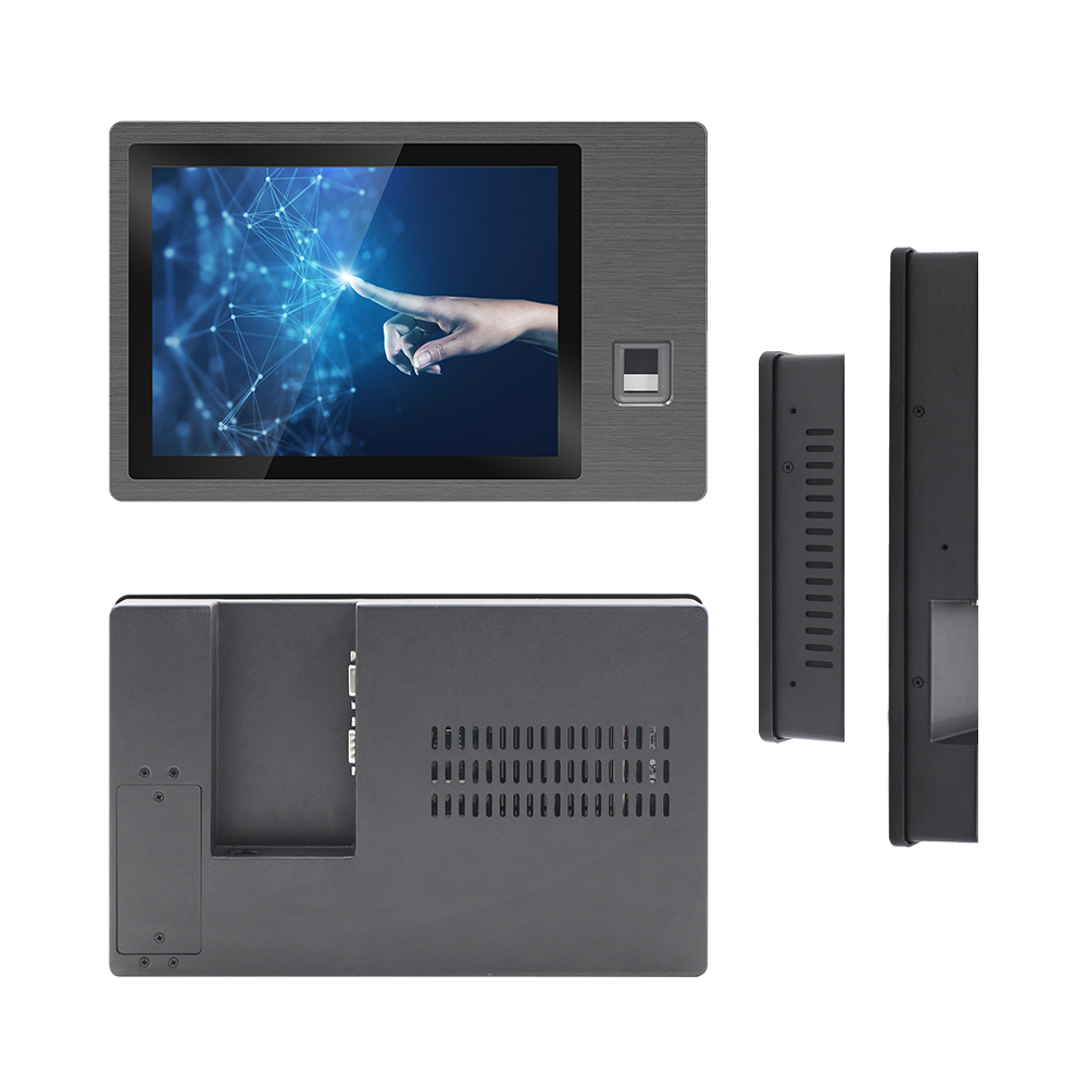
10.1″ Biometric Fingerprint Industrial Access Control PC
Engineered for high-security cleanrooms and automated manufacturing. Features an integrated optical fingerprint scanner, IEEE 802.3at PoE power input, IP65 waterproof front bezel, and 15 kV ESD surge isolation.
2. IEEE 802.3at PoE+ Transmission Line Voltage Drop and Thermal Budgets
Cleanroom wall cutouts lack space for bulky AC/DC transformers. System integrators standardize on Power-over-Ethernet (PoE) to deliver power and gigabit communication over a single Cat6 STP cable.
PoE Power Budget & Resistance Drop Formula: Source Voltage: V_PSE = 50.0V DC (IEEE 802.3at Type 2) Cable Loop Resistance (100m Cat6 23 AWG): R_loop ≈ 12.5 Ω Target Terminal Load Power: P_PD = 25.5 W Line Loss: P_loss = I^2 × R_loop → For I = 0.55 A, P_loss ≈ 3.78 W Terminal Delivered Voltage: V_PD = 50.0V – (0.55A × 12.5 Ω) = 43.125V (Safely above the 42.5V minimum threshold).
If low-grade 26 AWG or copper-clad aluminum (CCA) patch cables are deployed, loop resistance rises significantly, causing the delivered voltage to collapse below 42.5V during high-power camera and biometric illumination bursts, triggering infinite boot loops.
Cleanroom Access Control Terminal Specification Matrix
| Engineering Parameter | Standard Access Terminal | Engineered 10.1″ Biometric Panel PC |
|---|---|---|
| Biometric Sensor Window | Unprotected capacitive silicon (Prone to ESD damage) | 7H tempered optical prism with 15 kV TVS suppression |
| Power Architecture | 12V DC input only (Demands external power adapter) | Integrated IEEE 802.3at PoE+ (Class 4) & 9-36V DC terminal |
| Chemical Wipe-Down | ABS plastic frame cracks under concentrated IPA | Seamless anodized aluminum front bezel (IP65 rated) |
| Operating System | Closed proprietary firmware without remote management | Open Android / Linux Ubuntu / Windows 10 IoT API |
3. Commissioning Checklist for Cleanroom Installation
- Cable Verification: Measure DC loop resistance of the structured Cat6 line using a network cable analyzer before connecting the HMI. Ensure total round-trip resistance does not exceed 13.0 Ω.
- Perimeter Flush Mounting: Ensure the closed-cell neoprene perimeter gasket is compressed to exactly 30% of its initial height using flush mounting clamps to eliminate voids where airborne biological spores settle.
- Ground Continuity Check: Confirm resistance between the outer aluminum chassis and the building’s cleanroom equipotential ground ring measures less than 0.1 Ω.
Standardizing on PoE-powered biometric panel PCs simplifies cleanroom wall infrastructure while providing military-grade authentication security. Contact INNODA’s security hardware engineering team for SDK documentation, Wiegand interface pinouts, and custom biometric reader configurations.