
In automated manufacturing cells, water treatment skids, and energy management sub-stations, RS485 multi-drop serial networks remain the workhorse for connecting PLCs, variable frequency drives (VFDs), power meters, and environmental sensors. Under ideal conditions, a 2-wire differential RS485 bus supports reliable communication across distances exceeding 1,000 meters.
However, during active plant operation, maintenance technicians frequently encounter mysterious communication failures: periodic Modbus CRC check errors, frozen SCADA acquisition loops, and dropped node packets. In over 85% of field cases, serial failures stem from missing transmission termination, improper pull-up/pull-down bias resistance, or destructive ground potential differentials.
Following a systematic oscilloscope and multimeter diagnostic workflow restores reliable serial communication in minutes.
RS485 Serial Fault Diagnostic & Remediation Matrix
| Observed Bus Failure Symptom | Primary Root Cause | Diagnostic Verification Test | Field Corrective Action |
| Frequent Modbus CRC Checksum Errors | Signal reflections from missing bus termination | Measure resting line resistance (should be ~60 ohms) | Add 120-ohm termination resistor at both line ends |
| Communication Drops When Motor Starts | Inductive noise induced on unshielded serial lines | Check differential voltage noise on oscilloscope | Upgrade to shielded twisted pair (STP); ground one end |
| Intermittent Framing Errors at Idle | Floating differential bus voltage during line tri-state | Measure idle $V_A – V_B$ differential ($<200\text{ mV}$) | Install 560-ohm pull-up and pull-down fail-safe resistors |
| Blown RS485 Transceiver ICs | Common-mode ground loop exceeding $-7\text{V}$ to $+12\text{V}$ limit | Measure DC voltage between distant chassis grounds | Install galvanically isolated RS485 communication repeaters |
Step 1: Eliminating Transmission Line Reflections
When high-speed electrical signals reach the end of an untruncated wire, the impedance mismatch causes energy to reflect back down the cable, colliding with incoming data bits and corrupting Modbus CRC frames:
- The 120-Ohm Rule: Standard RS485 twisted-pair cabling has a characteristic impedance of approximately 120 ohms. To absorb signal energy without reflection, a 120-ohm, 1/4-watt resistor must be installed across Data+ (A) and Data- (B) lines at the two extreme physical ends of the bus.
- Field Verification: Power down the bus and measure resistance between lines A and B using a multimeter. If both ends are terminated properly, the reading will be approximately 60 ohms (two 120-ohm resistors in parallel). A reading of 120 ohms indicates one end is missing termination; a reading near infinity means zero termination exists.
- Deploying dedicated workstations like the Fanless Industrial Panel PC with 6x COM Ports provides native hardware UART controllers, allowing technicians to map independent, isolated serial loops across multiple physical DB9 ports rather than overloading a single serial bus.
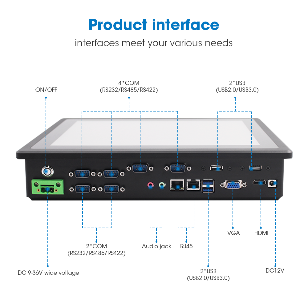
Fanless Industrial Panel PC with 6x COM Ports
Engineered with 6 × hardware DB9 serial ports (RS232/RS485/RS422), dual DC 9V–36V power input, true-flat IP65 front touch, and silent fanless aluminum heatsink chassis.
Step 2: Correcting Fail-Safe Bus Bias Resistors
When no master or slave device is actively transmitting, all transceivers enter a high-impedance listening state (tri-state):
- Without external biasing, electrical noise can pull the differential voltage ($V_A – V_B$) into the undefined threshold zone between $-200\text{ mV}$ and $+200\text{ mV}$, generating random ghost bytes.
- Remediation: Install fail-safe biasing—typically a 560-ohm pull-up resistor to +5V on Data+ and a 560-ohm pull-down to Ground on Data-. This ensures the bus maintains a stable differential of >200 mV during idle intervals.
Step 3: Breaking Ground Loops Across Distant Machinery
Connecting RS485 grounds between machines located hundreds of meters apart often creates dangerous ground currents:
- If the potential difference between two machine chassis exceeds the RS485 standard common-mode limit ($-7\text{V to }+12\text{V}$), transceiver chips overheat and fail permanently.
- Always ground cable shields at a single point only (usually at the central panel PC).
- For mid-sized machinery interfaces operating in tight electrical cabinets, deploying hardware such as the 13.3″ Aluminum Bezel Industrial Panel PC delivers protected downward-facing I/O wiring, isolating sensitive logic circuits from external electrical surges.
Preventive Routine for Automation Technicians
- Maintain Strict Daisy-Chain Topology: Never use “star” or “tree” wiring layouts for RS485; always route cables directly from device to device in a single continuous line.
- Verify Baud Rate Consistency: Ensure all slave instruments share identical baud rates, parity bits, and stop bits.
- Keep Serial Lines Away from High-Voltage Motor Runs: Maintain a minimum 300 mm clearance between RS485 communication cables and 480V VFD motor power leads.
Facing persistent Modbus communication timeouts, serial bus noise, or port configuration challenges? Contact INNODA’s serial automation engineering specialists for technical wiring schematics and hardware diagnostics.