
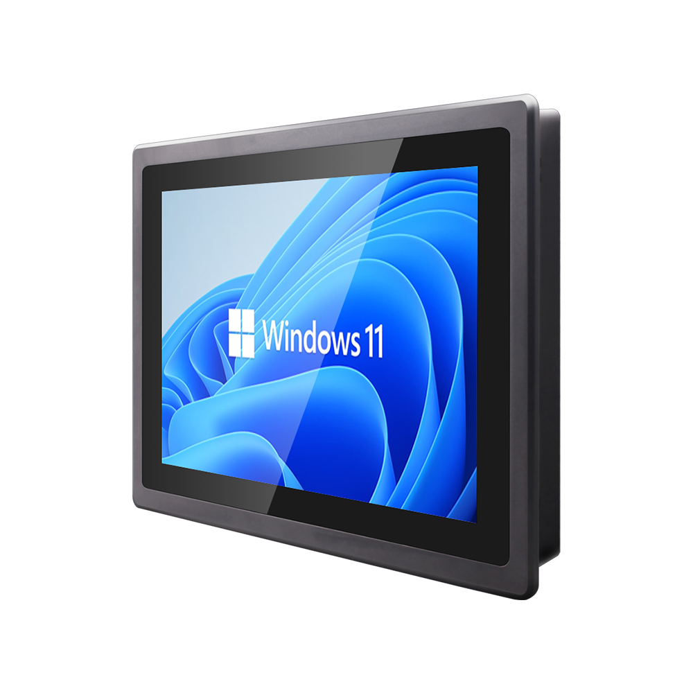
Despite the rapid expansion of Industrial Ethernet, EtherCAT, and wireless MQTT gateways across modern smart factories, serial communication (RS-232, RS-422, and RS-485) remains the workhorse of industrial control systems. Legacy CNC machining centers, precision weight scales, optical barcode scanners, variable frequency drives (VFDs), and programmable logic controllers (PLCs) rely heavily on serial fieldbuses for their deterministic response, protocol simplicity, and robust physical link stability.
However, running multiple concurrent serial communication channels on modern computing architectures frequently triggers driver lockups, COM port remapping, and ground loop faults under heavy manufacturing workloads.
1. Common-Mode Ground Differentials and Optical Isolation
The leading cause of field failure in industrial multi-drop RS-485 networks (which span distances up to 1200 meters) is electrical ground potential variance. When an industrial human-machine interface connects to remote field instruments powered by different electrical branch sub-panels, substantial DC and AC ground differentials build up across the shared signal ground line.
RS-485 Common-Mode Overstress Condition: Maximum Transceiver Common-Mode Tolerance: V_cm_max = -7V to +12V (TIA/EIA-485-A) Measured Branch Potential Offset: ΔV_ground = 18.5V AC (induced by VFD motor return currents) Result: Circulating ground current I_gnd > 2.5A across 24 AWG signal shield → Thermal destruction of UART driver IC.
Without hardware-level electrical isolation, heavy circulating ground currents flow directly through the transceiver ICs, causing burned UART drivers, intermittent CRC parity errors, and system lockups.
To guarantee 24/7 reliability on automated production floors, mission-critical systems like the Fanless Industrial Panel PC 6 COM Ports Windows 11 incorporate optocouplers and magnetic digital isolators providing 2.5 kV of electrical galvanic protection across all differential serial bus lines.
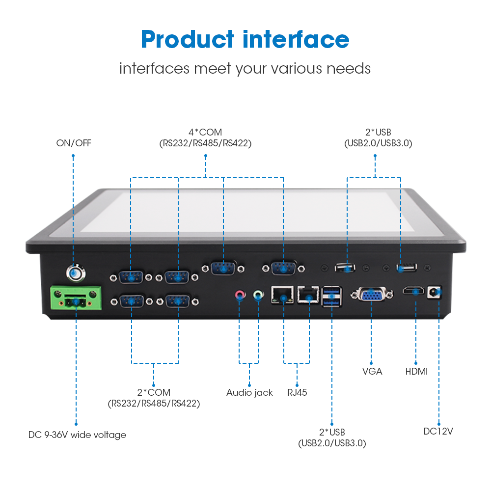
Fanless Industrial Panel PC (6 COM Ports & Windows 11 IoT)
Engineered for legacy CNC and SCADA automation lines. Features rugged CNC aluminum front bezel, 6 native RS232/RS485 COM ports, dual Intel Gigabit LAN, and wide DC voltage input with Windows 11 IoT support.
2. Native Hardware Super I/O vs. Virtual USB-to-UART Bridges
Consumer-grade computers and entry-level panel PCs frequently simulate serial connectivity using inexpensive USB-to-UART bridge controller chips. Following operating system reboots or Windows Updates, dynamic virtual COM reassignments renumber COM ports randomly, breaking SCADA driver paths and halting automated production lines.
- Native Super I/O Integration: The industrial motherboard integrates native Super I/O controllers mapped directly to the processor’s LPC bus, fixing hardware IRQ lines permanently for all 6 COM ports.
- BIOS-Selectable Transceivers: Operators can reconfigure physical ports between RS-232, RS-422, and 2-wire RS-485 modes directly through BIOS settings, eliminating manual hardware jumpers in the field.
- Heavy-Gauge Chassis Heat Dissipation: Robust finned aluminum rear housings provide pure conduction cooling for the multi-core processing subsystem, maintaining stable thermal headroom without fans.
Industrial Serial Bus Protocol Comparison Matrix
| Protocol Standard | Electrical Transmission Mode | Field Termination & Verification Metric |
|---|---|---|
| RS-232 | Single-ended voltage (±12V), max 15m line length | Verify TX/RX crossover and null modem pinning |
| RS-422 | Full-duplex differential (±5V), up to 1200m line length | Install 120-Ohm end-line termination resistor |
| RS-485 (2-Wire) | Half-duplex differential (±5V), multi-drop (32 nodes) | Verify 60-Ohm total parallel bus resistance |
| Galvanic Isolation | Non-isolated common ground in standard PCs | 2.5 kV optical/magnetic digital isolation per port |
| Driver Stability | USB bridge re-enumeration renames COM numbers | Hardwired LPC Super I/O with fixed physical IRQ lines |
3. Step-by-Step Multi-COM Diagnostic Routine
- Bus Termination Measurement: Disconnect AC power from all nodes. Measure DC resistance between Line A and Line B using a calibrated multimeter. A correctly terminated RS485 bus must read approximately 60 Ohms (reflecting two 120-Ohm termination resistors placed at physical bus extremities). A reading of 120 Ohms indicates a missing terminator, producing reflective signal ringing.
- Single-Point Shield Continuity: Verify that the shielded twisted pair (STP) drain wire is grounded at only one point (ideally at the panel PC master node). Double-ended shield grounding creates heavy ground loops that introduce continuous packet framing errors.
- Oscilloscope Waveform Verification: Probe differential lines under active communication. A healthy signal displays clear rectangular eye patterns with differential voltage swings greater than ±1.5V and rise times under 15% of the total bit duration. Excessive overshoot indicates impedance mismatching.
Standardizing factory lines on multi-serial fanless panel PCs prevents unexpected communication dropouts and protects sensitive automation hardware. Contact INNODA’s technical support team to review custom pinouts, pin-9 5V/12V power options, and isolation configurations.