Commercial fishing trawlers, offshore longliners, and sports fishing center-consoles operate in some of the most electronically hostile maritime environments. Bridge and flybridge navigation suites rely on high-brightness multi-size touch displays (ranging from 12.1-inch, 15-inch, and 18.5-inch to 21.5-inch widescreen formats) to visualize CHIRP sonar returns, Doppler radar tracks, and electronic vector chartplotters (such as TimeZero and Navionics). In open-cockpit helms, displays are permanently exposed to ocean spray, high ambient solar glare, and airborne salt fog.
Operating marine monitors over multi-season deployments introduces two primary degradation mechanisms: galvanic corrosion caused by electrical potential differences between dissimilar metals in wet salt air, and dielectric surface impedance degradation caused by dried salt crystals that induces false touches on projected capacitive (PCAP) glass. Establishing a rigorous preventative maintenance protocol preserves optical clarity and guarantees operational safety at sea.
1. Mixed Metallurgy Galvanic Corrosion & Faraday’s Metal Loss Mechanics
When an aluminum-alloy marine display chassis is mounted to a steel console bracket using stainless steel bolts in the presence of conductive seawater electrolyte (salinity ≈ 3.5%), a galvanic cell is formed. The more active metal (aluminum) functions as the sacrificial anode, losing mass over time:
Faraday’s Law of Galvanic Metal Loss: m_loss = (I_galv × t × M) / (z × F) Where: – Galvanic Leakage Current: I_galv ≈ 1.20 mA = 1.20 × 10^-3 A (typical unisolated marine circuit). – Annual Service Time: t = 365 days × 24 h × 3600 s = 31,536,000 seconds. – Molar Mass of Aluminum (Al): M = 26.98 g/mol = 0.02698 kg/mol. – Valence Charge Number: z = 3 (for Al3+ ion oxidation). – Faraday’s Constant: F = 96,485 C/mol. Annual Sacrificial Aluminum Mass Loss Calculation: m_loss = [ (1.20 × 10^-3) × 31,536,000 × 0.02698 ] / [ 3 × 96,485 ] m_loss = 1021.0 / 289,455 ≈ 3.527 × 10^-3 kg ≈ 3.53 grams of aluminum stripped annually. Mechanical Impact: Unchecked galvanic action pits VESA mounting threads and chassis perimeter joints, loosening water-sealing O-rings and allowing salt water to flood internal electronics.
To eliminate galvanic degradation, marine installations must break the electrical conduction path between dissimilar metals by utilizing non-conductive fluoropolymer (PTFE) or nylon shoulder isolation washers between all mounting brackets, fasteners, and aluminum chassis points.
To deliver lasting ocean-going durability, commercial vessel operators standardize on the 12.1″-21.5″ Marine Fishing Sonar Touch Monitor, which features corrosion-resistant marine-grade aluminum alloys, full optical wet bonding, and dedicated galvanic isolation hardware.
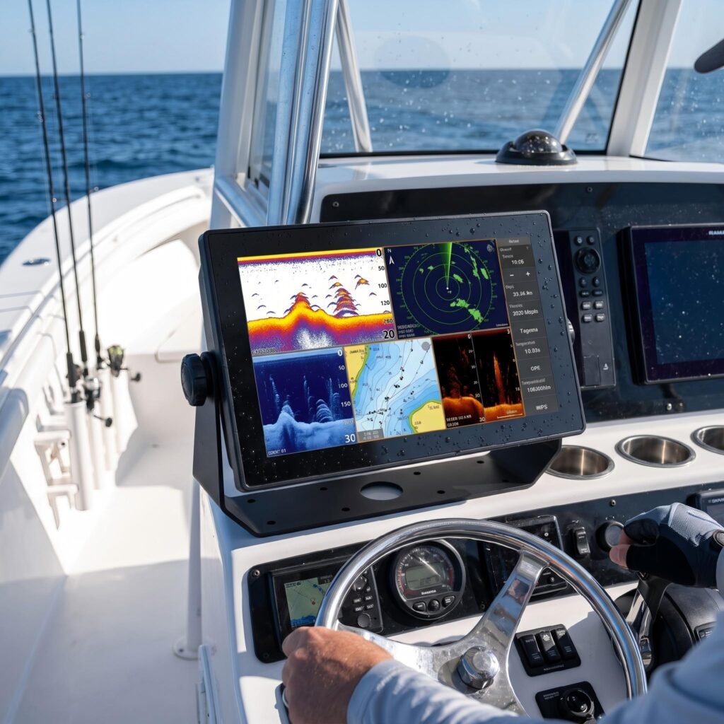
12.1″-21.5″ Marine Fishing Sonar Touch Monitor
Built for commercial fishing trawlers, marine chartplotters, and offshore sonar consoles. Features 1000-1500 nits sunlight readability with LOCA optical bonding, 0-100% smooth night dimming, marine galvanic corrosion protection, and full IP65/IP67 waterproof front sealing.
2. Dielectric Salt Crystal Creep & Optical Wet Bonding Maintenance
Maintaining clear sonar visibility under tropical sunlight requires specialized care:
- Dielectric Salt Film Dissolution: As sea spray evaporates on the display face, microscopic sodium chloride crystals form a conductive surface lattice. This alters the local dielectric constant (ε_r), causing the touch controller to register phantom clicks. Rinsing the screen with fresh deionized water dissolves the salt lattice, restoring normal capacitive calibration.
- LOCA Optical Wet Bonding Inspection: Marine displays feature Liquid Optical Clear Adhesive (LOCA) between the LCD and cover glass. Inspect perimeter bond lines annually for delamination bubbles or yellowing caused by extreme solar UV radiation.
- Ultra-Deep Night PWM Dimming: Marine night watches require backlight output to dim smoothly below 1 nit without flickering, preserving the bridge watchstander’s scotopic night vision while navigating harbor channels.
Marine Bridge Display Diagnostic Matrix
| Diagnostic Checkpoint | Inspection Procedure | Corrective Maintenance Action |
|---|---|---|
| Mounting Bolt Isolators | Check nylon shoulder washers for cracking or crushing | Replace with fresh marine-grade PTFE isolation bushings |
| Touchscreen Salt Residue | Visual check for white crusting causing erratic clicks | Rinse with warm freshwater; wipe with microfiber cloth |
| LOCA Optical Bonding | Inspect display corners under sunlight for air bubbles | Verify hermetic seal prevents optical edge separation |
| Video Connector Pins | Inspect DVI/HDMI/VGA pins for green verdigris tarnish | Clean with electrical contact cleaner; apply dielectric grease |
| Chassis Sacrificial Anode | Check continuity to helm sacrificial zinc bonding strap | Ensure bonding resistance ≤ 0.05 Ω to vessel ground |
3. Semi-Annual Marine Vessel Preventative Maintenance Protocol
- Freshwater Salt Flush: At the conclusion of every offshore fishing voyage, rinse the entire monitor front face and perimeter chassis with low-pressure clean freshwater (< 2 bar) to dissolve dried salt deposits. Never use harsh petroleum solvents or ammonia glass cleaners.
- Fastener Galvanic Check: Remove console mounting fasteners annually to inspect for white aluminum hydroxide powder (galvanic pitting). Re-apply anti-seize marine barrier compound before re-torquing.
- Dimming Control Calibration: Test the rotary potentiometer or OSD dimming controls across the full 0% to 100% range, verifying smooth luminance transition from 1500 nits down to < 1 nit without backlight step jitter.
Implementing a structured preventative maintenance schedule for marine fishing sonar touch monitors preserves optical contrast and prevents galvanic failure during critical offshore voyages. Contact INNODA’s marine electronics engineering team to request ECDIS calibration profiles, optical bonding durability reports, and custom helm mounting bracket kits.